

Raspberry Pi
| Date: | 2013-08-04 |
|---|
The Raspberry Pi is a small and inexpensive ARM-based single-board-computer, which runs Linux and which is currently produced in large quantities.
Although the Raspberry Pi is much slower than current PCs and even a bit slower than the Intel Atoms, it's fast enough for a wide field of applications. It's especially suited as a small embedded PC, e.g. for automatization tasks.
|
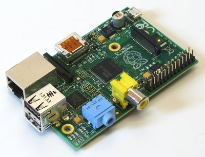
| Raspberry Pi photo, Model B, Rev. 2 |
This page should summarize or link some technical information and useful hints about the Raspberry Pi. More and more detailed information can be found in the Raspberry Pi blog, the Raspberry Pi wiki, the Raspberry Pi forum and several other websites.
But please note, that:
- the Raspberry Pi foundation unfortunately publishes only little documentation, so most of the information not official,
- some information was taken from other sites and was not verified again, and
- the technical data etc. of the Raspberry Pi may change.
If you find any errors on this page, please notify us by email.
Contents
Specifications
| Model B, Rev. 2/512MB | Model A | |
|---|---|---|
| System-on-a-chip | Broadcomm BCM2835 / BCM2708 family | |
| CPU | 700 MHz ARM11 (ARM1176JZF-S) | |
| GPU | Broadcomm VideoCore IV | |
| RAM | 512 MB | 256 MB |
| Storage | SD-card | |
| USB 2.0 | 2 (internal Hub) | 1 |
| Network | 10/100 MBit Ethernet | -- |
| Video-Outputs | HDMI, Composite (not simultaneously) | |
| Audio-Outputs | 3.5mm jack, HDMI | |
| GPIO | 17 (P1) + 4 (P5) | |
| Power | 5V via Micro-USB- or GPIO-connector | |
| Power Usage | 700mA / 3.5W | 500mA / 2.5W |
| Size | 85.60mm * 56.0mm * 21mm | |
| Weight | about 45g [1] | ? |
| Temperature | 0..70°C (probably) | |
| Operating System | Linux | |
| Price | about $35 + VAT | about $25 + VAT |
See also: http://elinux.org/RPi_Hardware
| [1] | 45g according to specification, measured value: about 40g |
Models
There are several different models and revisions of the Raspberry Pi. But the currently sold Raspberry Pis should all be Model A or B in revision 2.
- Model B:
- Revision 2 / 512MB: current version
- Revision 2 / 256MB: only 256 MB RAM
(The first Raspberry Pis of revision 2 only contained 256 MB RAM. But there were probably not very many of them.) - Revision 1.0+ECN0001
- Revision 1.0: first Version, like current version, but
- with only 256 MB RAM
- without mounting holes
- without connector P5 (additional I/O-pins)
- without connector P6 (reset)
- with some swapped GPIOs and swapped I2C-buses
(GPIO0<->GPIO2, GPIO1<->GPIO3, GPIO21<->GPIO27) - with some more minor differences [2]
- Model A: like Model B, Revision 2, but
- without Ethernet
- with only 1 USB connector
- with only 256 MB RAM
On running Raspberry Pis, model and revision can be extracted from the Revision :-entry of /proc/cpuinfo: [3]
| /proc/cpuinfo | model / revision |
|---|---|
| Revision: | |
| 0x02 | Model B, Revision 1.0 |
| 0x03 | Model B, Revision 1.0+ECN0001 |
| 0x04 / 0x05 / 0x06 | Model B, Revision 2.0, 256 MB RAM |
| 0x07 / 0x08 / 0x09 | Model A, Revision 2.0, 256 MB RAM |
| 0x0d / 0x0e / 0x0f | Model B, Revision 2.0, 512 MB RAM |
In addition, the manufacturer can be extracted:
- 0x04 / 0x08 / 0x0e: Sony
- 0x05 / 0x09 / 0x0f: Egoman
- 0x06 / 0x07 / 0x0d: Quisda
| [2] | All differences can be found at http://www.raspberrypi.org/archives/1929. |
| [3] | http://elinux.org/Rpi_HardwareHistory, http://www.raspberrypi.org/phpBB3/viewtopic.php?f=63&t=32733 |
Dimensions
- PCB-Size:
- Model B: 85.6mm * 56mm * 21mm
- Model A: 85.6mm * 56mm * ??
- height (Model B): measured about 21.5mm, with
- about 16mm above the PCB
- about 1.6mm thickness of the PCB
- about 3.8mm below the PCB (SD-card-slot)
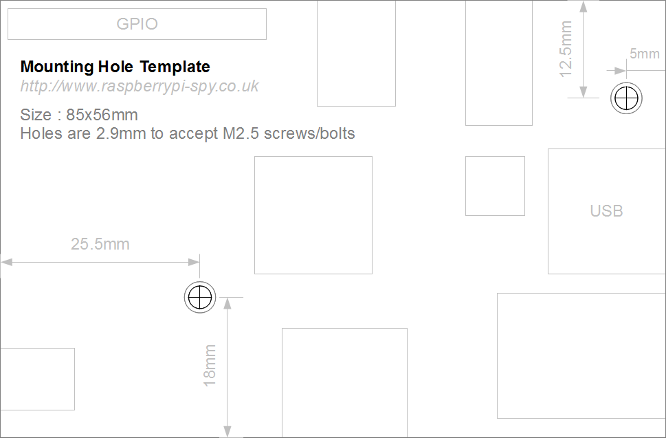
- mounting holes (Rev. 2) [4]:
- quantity: 2
- diameter 2.9mm (for M2.5; some M3-screws might work, too)
- distances from the Micro-USB-corner:
- x 25.5mm, y 18.0mm
- x 80.1mm, y 43.6mm
Except these dimensions, there unfortunately aren't any official positions of the connectors. But some users have measured these positions with a calliper, and created a drawing including these dimensions:
- http://openlab.com.au/raspberry-pi-dimensions-and-pinout/,
http://openlab.com.au/wp-content/uploads/2013/04/Raspberry_Pi_Dimensions.png
| [4] | http://www.raspberrypi.org/archives/2691,
http://www.raspberrypi.org/wp-content/uploads/2012/12/Raspberry-Pi-Mounting-Hole-Template.png |
I/O-connectors / GPIOs
See also: http://elinux.org/Rpi_Low-level_peripherals
The numbers of the GPIOs is taken from the internal numbers in the Broadcomm processor (e.g. GPIO7). But since this isn't very intuitive, we usually name them by their position on the connector (e.g. P1-26).
Please note that all GPIOs work with 3.3V, and are not 5V-tolerant! If 5V-tolerant inputs are needed, additional external electronics (e.g. a voltage divider or a CPLD) should be added, or an appropriate extension-board (e.g. our AdvaBoard RPi1) should be used. Extension-boards additionally can simplify the connectors by e.g. using separate connectors for digital-/analog-I/O, SPI, I2C, RS232 etc. (like our AdvaBoard RPi1).
|
|
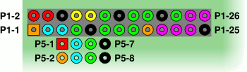
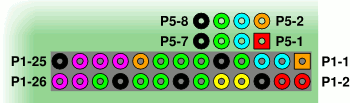
| GPIO-pins, RPi-corner top-left | GPIO-Pins, RPi-corner bottom-right |
- P1:
17 I/Os
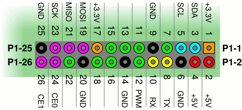
GPIO-connector P1, RPi-corner bottom-right pin GPIO-number default function alternative functions P1-1 – +3.3V output, max. 50mA P1-2 – +5V / power supply P1-3 GPIO2 [r] I/O I2C1 SDA P1-4 – +5V (=P1-2) P1-5 GPIO3 [r] I/O I2C1 SCL P1-6 – Ground P1-7 GPIO4 I/O GPCLK0, ARM-JTAG-TDI P1-8 GPIO14 UART-TX I/O P1-9 – Ground P1-10 GPIO15 UART-RX I/O P1-11 GPIO17 I/O P1-12 GPIO18 I/O PWM P1-13 GPIO27 [r] I/O ARM-JTAG-TMS P1-14 – Ground P1-15 GPIO22 I/O ARM-JTAG-TRST P1-16 GPIO23 I/O ARM-JTAG-RTCK P1-17 – +3.3V output (=P1-1) P1-18 GPIO24 I/O ARM-JTAG-TDO P1-19 GPIO10 I/O SPI MOSI P1-20 – Ground P1-21 GPIO9 I/O SPI MISO P1-22 GPIO25 I/O ARM-JTAG-TCK P1-23 GPIO11 I/O SPI-SCK P1-24 GPIO8 I/O SPI-CE0 P1-25 – Ground P1-26 GPIO7 I/O SPI-CE1 By default, GPIOs P1-8 and P1-10 are configured as UART.
[r] (1, 2, 3) Revision 1 instead uses:
- P1-3: GPIO0, I2C0 SDA
- P1-5: GPIO1, I2C0 SCL
- P1-13: GPIO21
- P5 (Rev. 2, by default without connector):
4 I/Os, intended as 2nd I2C or PCM-output
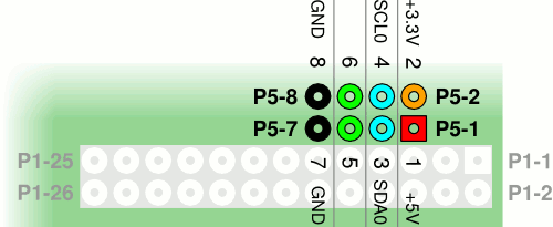
GPIO-connector P5, RPi-corner bottom-right pin GPIO-number default function alternative functions P5-1 – 5V P5-2 – +3.3V (max. 50mA, together with P1) P5-3 GPIO28 I/O I2C0 SDA, PCM CLK P5-4 GPIO29 I/O I2C0 SCL, PCM FS P5-5 GPIO30 I/O PCM DIN P5-6 GPIO31 I/O PCM DOUT P5-7 – Ground P5-8 – Ground Please note that P5 is intended for soldering a connector to the bottom side, so the pins are numbered in a different order than the pins on P1.
Performance
- CPU:
- The computing power of the Raspberry Pi is roughly equivalent to a 300MHz Intel Pentium2 [5].
- Overclocking:
The Raspberry Pi may be overclocked (without losing warranty) to up to 1 GHz. But it should be checked for each single Raspberry Pi if it still runs stable at these frequencies. In addition, the combination of overclocking and SD-cards of class 6 or 10 often leads to unstable systems and data-/filesystem-corruption. [6]
We generally would not recommend to overclock the Raspberry Pi. If SD-cards of class 6 or 10 are used, we strongly discourage overclocking.
- GPU:
- The GPU is capable of 1 GPixel/s / 1.5GTexel/s / 24 GFLOPs, which corresponds to Xbox 1 level [5].
- USB:
- The Raspberry Pi can transfer about 30 MB/s over USB [7].
But note that usually several devices use USB, since e.g. Ethernet on the Raspberry Pi is connected via USB, and so the transfer rate for every device is usually lower.
Some benchmarks can be found at http://elinux.org/RaspberryPiPerformance.
| [5] | (1, 2) http://elinux.org/RPi_FAQ#How_powerful_is_it.3F |
| [6] | http://www.raspberrypi.org/archives/tag/overclocking,
http://elinux.org/RPi_FAQ#Will_it_overclock.3F, http://elinux.org/RPiconfig#Overclocking |
| [7] | tested with a fast USB-stick: root@raspberrypi:~# dd if=/dev/sda of=/dev/null bs=32M count=10 iflag=direct 10+0 records in 10+0 records out 335544320 bytes (336 MB) copied, 10.6428 s, 31.5 MB/s |
Power Consumption
specified power consumption:
- Model A: 500mA
- Model B: 700mA
measured power consumption (Model B, Rev. 1):
| test-condition | current | notes |
|---|---|---|
| boot | 0.3 A | without connected periphery (HDMI, keyboard etc.) |
| LAN + SSH | 0.3 A | with network-cable, no additional periphery |
| LAN + SSH + 100% CPU | 0.3 - 0.4 A | " |
| LAN + SSH + USB-WLAN-stick | 0.50 - 0.55 A | " |
Linux
The Raspberry Pi runs a normal, full-featured Linux [8]. Linux-images for the Raspberry Pi can be downloaded from the Raspberry-Pi-website. There are currently official images for Debian Linux, Raspbian, Arch Linux and Pidora; additionally, many Linux-distributions include Raspberry Pi-support, and there is a installer named NOOBS:
download Linux-image / NOOBS:
copy Linux-image to SD-card:
After downloading the image, it must be transferred to the SD-card, as described on the download-page or in the wiki as easy way and advanced way. If you used Linux and dd, make sure to use the parameter oflag=direct, since it's a lot slower without:
dd if=2013-07-26-wheezy-raspbian.img of=/dev/sd... bs=1M oflag=direct
Put SD-card into Raspberry Pi and connect the Raspberry Pi to the power supply.
For the first boot, you usually need a connected HDMI-monitor and a USB-keyboard to initially configure the Raspberry Pi. If you want to boot and initially configure the Raspberry Pi without a monitor/keyboard, you can use a serial console, as described below.
Configure the Raspberry Pi, e.g. by sudo raspi-config (If a monitor is connected, the raspi-config-configuration-dialog is displayed on the 1st boot.)
The boot time of the Raspberry Pi heavily depends on the used operating system and its configuration. Especially the use of systemd, like activated by default by e.g. Arch Linux, may drastically reduce the boot time (e.g. 13s instead of 24s).
| [8] | In contrast to several other small ARM-computers (like routers, the Carambola or Gnublin), which often run a special embedded-Linux (mostly OpenWRT). |
SD-cards
- Compatibility:
- According to http://elinux.org/RPi_SD_cards, some SD-cards are incompatible with the Raspberry Pi; especially some class 10 cards seem to be problematic.
- Speed:
The speed of the SD-card can influence the Raspberry Pi performance.
The reading speed of many SD-cards is quite similar; the main difference is the writing speed, especially with many small files. Fast cards achieve at least 1 MB/s even with small files, medium-fast ones several 100 KB/s, slow ones less than 100 KB/s.
The results of own test can be found in the table below. Information about other SD-cards can be found in the Raspberry Pi wiki at http://elinux.org/RPi_SD_cards.
Test-Results:
SD-cards:
| vendor | model | size | class | RPi- | read [MB/s] | write [MB/s] | boot-time | |||||||
|---|---|---|---|---|---|---|---|---|---|---|---|---|---|---|
| comp.? | RPi | CrystalDiskMark | RPi | CrystalDiskMark | Debian | Arch | ||||||||
| dd | seq. | 512K | 4k | dd | seq. | 512k | 4k | |||||||
| Sandisk | Ultra 15MB/s | 2 GB | + | 22.6 | 19 | 18.5 | 4.3 | 14.8 | 12 | 3.1 | 0.029 | 27s | ||
| Samsung | MB-SS4GA | 4 GB | Class 4 | + | 22.0 | 19 | 18.0 | 3.3 | 6.7 | 7.0 | 1.0 | 0.23 | 26-27s | |
| Samsung | MB-SS8GA | 8 GB | Class 6 | + | 22.6 | 19 | 18.0 | 3.8 | 11.7 | 11 | 1.0 | 0.24 | 26s | |
| Samsung | MB-SSAGA | 16 GB | Class 6 | + | ||||||||||
| Sandisk | SDSDX-016G | 16 GB | Class U1 | + | 23.0 | 19 | 18.5 | 4.3 | 21.2 | 14 | 3.1 | 1.2 | 24s | 13s |
microSD-cards:
| vendor | model | size | class | RPi- | read [MB/s] | write [MB/s] | boot-time | |||||||
|---|---|---|---|---|---|---|---|---|---|---|---|---|---|---|
| comp.? | RPi | CrystalDiskMark | RPi | CrystalDiskMark | Debian | Arch | ||||||||
| dd | seq. | 512K | 4k | dd | seq. | 512k | 4k | |||||||
| PNY | SD-C02G | 2 GB | partly | 18.2 | 19 | 17 | 3.0 | 6.8 | 1.5 | 0.019 | 31s | |||
| Samsung | plus MB-MP 8G | 8 GB | Class 6 | + | 17.5 | 15 | 15 | 5.3 | 10 | 2.0 | 0.019 | 27s | 17s | |
| Transcend | TS16GUSDHC6 | 16 GB | Class 6 | + | 22.7 | 19 | 19 | 4.4 | 6.8 | 1.0 | 0.047 | 26s | ||
| Sandisk | Ultra (SU32G) | 32 GB | Class U1 | + | 21.4 | 19 | 19 | 3.5 | 9.4 | 7.6 | 1.8 | 25s | ||
(currently available cards are marked in bold)
Test-conditions:
- RPi read/write: measured under 2012-10-28-wheezy-raspbian.img with dd if=/dev/... of=/dev/null bs=32M count=10 iflag=direct and dd of=/dev/... if=/dev/zero bs=32M count=10 oflag=direct.
- other read/write-rates: sequential read/write, 512K random and 4K random; measured on a Windows-PC with CrystalDiskMark and a fast USB2.0-card-reader (Conrad 60-in-1, Model UC420).
- boot-time: Time until the login-prompt on the console, Debian: 2012-10-28-wheezy-raspbian.img, Arch: archlinux-hf-2012-09-18.img
- Like all benchmarks, the results should be used with care.
- Size:
Since the SD-card-holder is located at the edge of the Raspberry Pi, SD-cards protrude the Raspberry Pi board by about 17.5mm. If this is a problem, a microSD-card with a special adapter can be used:
- pIO: http://www.quilix.com/pio
- Adafruit microSD-adapter: http://www.adafruit.com/products/966
Note that with this adapter, the microSD-cards still protrudes the Raspberry Pi board; in return, the microSD-card can be changed without removing the adapter. - Comparison of pIO and Adafruit: http://www.recantha.co.uk/blog/?p=2922
- self-built: http://code.google.com/p/raspberry-pi-rs-micro-sd-adapter/
- others: http://www.diygadget.com/low-profile-microsd-to-sd-card-adapter-for-raspberry-pi.html,
http://afterthoughtsoftware.com/products/rassd
Alternatively, some SD-cards can be cut to make them shorter: The case of some SD-cards are only filled partly with electronics, and the rest is empty. So, these cards could be cut in half (and the case could be sealed again afterwards), and the remaining part is only about half as long as the original card. Especially SD-cards from SanDisk can be used for this, since they often have a half-transparent case, so you can see the empty part of the case (see photo).
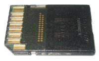
half-empty SanDisk SDSDX-016G
(click to enlarge)

serial console / serial login (via USB)
The official Raspberry Pi SD-card-Linux-images assume, that the Raspberry Pi is started for the first time with a connected HDMI-display and USB-keyboard, and that the Raspberry Pi is then initially configured thereby. After configuration, the Raspberry Pi then can also be used without display/keyboard and administrated over the network.
But if you don't want to connect a HDMI-display and a USB-keyboard for the 1st boot, you have to:
either modify the Linux-image, e.g. by adding a network-configuration. However, advanced Linux-skills may be necessary to accomplish this.
or use the serial console, and login/configure the Raspberry Pi from an other computer. Some adapters are needed therefor.
By the way, a serial console is not only useful during installation, but also later for administration purposes, if the Raspberry Pi (permanently or temporarily) cannot be reached over the network.
|
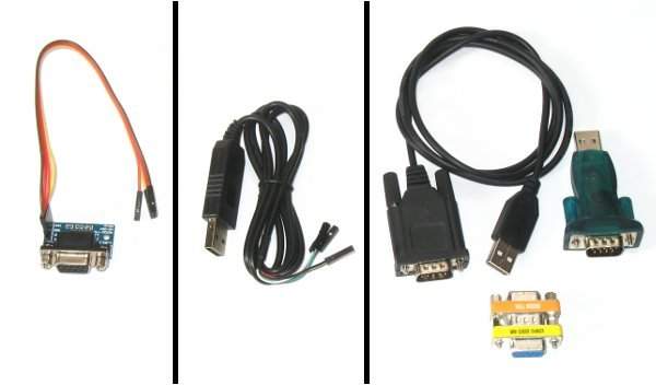
| RS232-TTL-adapter (left), USB-RS232-TTL-adapter (center), 2 USB-serial-adapters + null modem (right) |
For the 2nd way, you normally need some wires and a RS232-TTL-adapter (or a USB-RS232-adapter), to connect the serial port on the GPIO-header of the Raspberry Pi and the serial port of an other computer. [9] After connecting to the Raspberry Pi, you'll (a) see all boot-messages of the kernel and (b) can log in over the serial connection.
Alternatively, 2 USB-serial-adapters and a so-called null modem can be used. The Linux-image than has to be modified slightly. In this case, you don't see any boot-messages, and can "only" login, but this is often sufficient. The advantage of this solution is, that it altogether is usually simpler: You don't need to connect single wires, you don't need access to the GPIO-header and no configured UART-pins (P1-8 / P1-10), it also works with cased Raspberry Pis and it uses more common adapters.
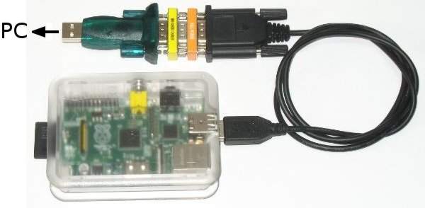
|
| serial console via USB |
Instructions for a serial login via USB:
- Modify Linux-image:
connect SD-card to a PC (e.g. via card-reader)
Add the following line to the end of the file /etc/inittab on the SD-card:
# for Debian Linux:
T1:23:respawn:/sbin/getty -L ttyUSB0 115200 linux

# for Arch Linux:
# S1:12345:respawn:/sbin/agetty ttyUSB0 115200 linux
remove SD-card, and connect it to the Raspberry Pi
Connect USB-serial-adapters:
Connect 2 USB-serial-adapters via null modem and connect the 2 ends (USB-A-connectors) to the Raspberry Pi and the PC.
If the PC still has a serial port, the null modem can directly connected to this port and no 2nd USB-serial-adapter is needed. In this case, /dev/ttyUSB0 has to be replaced by /dev/ttyS0 in the following instructions.
Some USB-serial-adapters are currently not yet recognized by the Raspberry Pi. In these cases, a different adapter (with a different chipset) should be used.
Open serial console:
On Linux, several different programs can be used:
program command-line exit screen screen /dev/ttyUSB0 115200 Ctrl-A minicom minicom -b 115200 -o -c on -D /dev/ttyUSB0 Ctrl A Z q picocom picocom -b 115200 -i -r /dev/ttyUSB0 Ctrl-A Ctrl-X putty putty -serial -sercfg 115200 /dev/ttyUSB0 close window gtkterm gtkterm, Configuration -> Port close window Information about further programs and Windows can be found at http://elinux.org/RPi_Serial_Connection.
Please note, that:
- minicom has problems with the colors of raspi-config
- putty and gtkterm run under X and can be configured graphically (port: /dev/ttyUSB0, speed: 115200)
- If several USB-serial-adapters are used on a PC, or if a adapter was connected and disconnected several times, /dev/ttyUSB0 may have to be replaced by /dev/ttyUSB1, /dev/ttyUSB2 or similar.
- The Linux-user on the PC usually has to be a member of the group "dialout", to access USB-serial-adapters. This can be accomplished by adduser USERNAME dialout as root and newgrp dialout as user.
- Boot Raspberry Pi. As soon as the Raspberry Pi has booted, a login prompt appears in the screen/minicom/picocom/putty/gtkterm-window on the PC. After logging in, the Raspberry Pi can be initially configured, e.g. by using sudo raspi-config.
| [9] | http://elinux.org/RPi_Serial_Connection |
Bugs
- I2C "clock-stretching" bug: I2C-sensors and other I2C-devices, which use "clock-stretching", cannot be used reliably directly on the Raspberry Pi, due to a bug in the Raspberry Pi.
Extensions
Since the Raspberry Pi is very popular and suited for many applications, there are lots of extension-boards. An overview of existing extensions can be found in the Raspberry Pi wiki: http://elinux.org/RPi_Expansion_Boards
We also offer some extensions, e.g. the AdvaBoard RPi1 (incl. real-time-clock, 5V-tolerant I/O, analog-inputs, an optional TFT-display, separate connectors for the different interfaces, power-management etc.).
TFT-Display
One of the most interesting extensions for the Raspberry Pi is a TFT-display. Such displays can be connected in different ways to the Raspberry Pi:
- via GPIO (up to 7.0")
- via per HDMI (from 7.0" upwards)
- via Composite Video (RCA connector)
- via USB (unfortunately, this is not really possible, since all USB-displays we know only work under Windows)
- via DSI (unfortunately, this is not really possible, since there is no documentation about the DSI-port of the Raspberry Pi, and there probably never will)
See also: http://elinux.org/RPi_Screens
HDMI
HDMI-displays begin at 7.0". The HDMI-displays can be divided into:
- small displays with max. 15" (e.g. from Faytech), often with touchscreen, but which are relatively rare,
- larger displays beginning at about 17"/19", usually without touchscreen, which are available as standard computer monitors, and which are often cheaper than the smaller displays.
Instead of a HDMI-display you can also use a DVI-display and a simple DVI-HDMI-adapter. If you use an VGA-HDMI-converter (about 10 - 30€), you can even connect a VGA-display to the Raspberry Pi.
GPIO / SPI
TFT-displays for connection to the GPIO-pins or SPI exist from about 1.5" up to 7.0". Many of these displays contain a (resistive) touchscreen. These displays can be connected to the Raspberry Pi in two different ways:
- directly connected to the Raspberry Pi:
Small displays with a SPI- or parallel 8-bit-interface can often be connected directly to the Raspberry Pi GPIOs. There's a project which follows this aim and additionally develops framebuffer-drivers for these (1.5" - 3.2") displays: - connected via extension-board:
The usually better, easier-to-use and more flexible (but also a bit more expensive) way is to connect the display with an appropriate extension-board. This allows more different displays and higher framerates -- depending on how the extension-board is designed. We know of the following extensions:- 1.8": 1.8inch TFT LCD + Switch Shield
- 2.4"/2.8": Raspberry PI LCD Adapter Kit for ITDB02 displays
- 2" - 7": our AdvaBoard RPi1 with TFT-displays in the sizes 2.4", 3.2", 4.3", 5.0" and 7.0"
Here, it would even be possible to connect several displays simultaneously to the Raspberry Pi.
Composite
In principle, displays could also be connected to the composite video (NTSC / PAL) output of the Raspberry Pi, e.g. TV monitors or small video monitors as e.g. used in cars. Such monitors are usually cheap, but the display quality is much worse than with HDMI- or GPIO/SPI-displays. Additionally, their pixels are often not square (!).
We would generally discourage from using them. They only may be useful as cheap video-displays; but they're not suited for anything else in our opinion.
PoE (Power over Ethernet)
The Raspberry Pi can be powered by PoE (Power over Ethernet), if you use a PoE-splitter (with an output-voltage of 5V) and an adapter from the PoE-splitter-power-connector to Micro-USB.
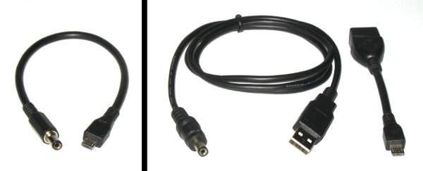
|
| PoE-power-adapters: self-made adapter (left), bought adapters (right) |
Often, PoE-splitters use a coaxial power connector (also known as barrel connector or DC plug) with 5.5/2.1mm. In the picture above, you can see (a) an appropriate self-made adapter for the Raspberry Pi and (b) a combination of two off-the-shelf adapters [10]. But before connecting the power-adapter, make sure that the output-voltage of the PoE-splitter is set to 5V!
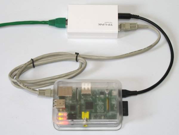
|
| PoE + Raspberry Pi |
Please note that PoE can deliver max. 12.95W (PoE+: max. 21.9W). With the specified power usage of the Raspberry Pi (5V, 700mA), max. 3 Raspberry Pis may be powered simultaneously over the same PoE-network.
| [10] | e.g.:
|
Where to buy
Single Raspberry Pis for our products can be directly bought from us. However, larger quantities can be bought a bit cheaper from several online-shops, e.g.:
- Farnell (only for business-users)
- RS Components
- Reichelt
More shops can be found at http://elinux.org/Buying_RPi.
Links
- Raspberry Pi main page / blog
- Raspberry Pi FAQs
- Raspberry Pi wiki
- Raspberry Pi forum
- Raspberry-Pi-page of Farnell
- Raspberry-Pi-page of element14
- Raspberry-Pi-page of RS
