

AdvaBoard RPi1 - Raspberry Pi extension board


(click to enlarge)
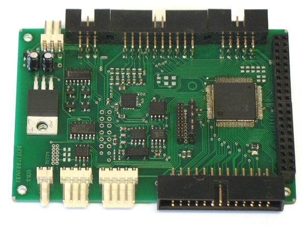
AdvaBoard RPi1
The AdvaBoard RPi1 is an extension-board for the Raspberry Pi, which converts the Raspberry Pi to a universal small embedded industrial PC, and which contains:
- TFT-display-interface (for a 2.4" / 3.2" / 4.3" / 5.0" / 7.0" TFT-display incl. touchscreen)
- real-time clock
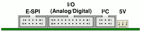
- extended interfaces (I2C, extended SPI, digital- and analog-I/Os, RS-232, RS-485 on separate connectors
- 5V-tolerant inputs and outputs (except I2C)
- power-management / battery power
- JTAG-/C2-programmer
- software-library + example programs
- framebuffer-driver for Linux
- optional periphery: sensors, extensions-boards, displays, automatization components (e.g. motors), measurement technology, ...
Details
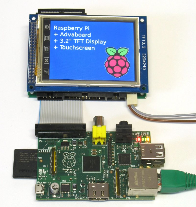
The AdvaBoard RPi1 is an extension-board for the Raspberry Pi, incl. a real-time-clock, various (5V-tolerant) interfaces on dedicated connectors, digital- and analog-I/Os, an integrated power-management incl. battery power and an optional TFT-display (2.4" - 7.0") with touchscreen. So, the AdvaBoard widely extends the possible field of application of the Raspberry Pi and upgrades it to an universal small embedded industrial PC.
It's easy to connect different sensors, additional I/Os, CPLD- and microcontroller-boards, control components (e.g. motors) and even further TFT-displays on the interfaces (I2C, E-SPI, RS-485, RS-232).
The provided software includes a complete program library for C and Python and some open example programs, which allow a very fast startup, and may serve as base for own programs. Additionally, the Raspberry Pi and the AdvaBoard can be controlled via JSON-RPC over a network connection. Besides, a framebuffer-driver is available, so the TFT-display (which is connected to the AdvaBoard) can be used as default Linux-display.
Moreover, we can offer an extensive support incl. development support, modified hardware (e.g. adapted input-ranges of the analog-inputs) and specialized firmware (CPLD, microcontroller) for your application.
Interfaces:
- I2C / SMBus, 3.3V, incl. interrupt-input and battery power
- 10 digital-I/Os, 3.3V, 5V-tolerant, incl. PWM, counter, optional hardware-supported processing by the CPLD etc.
- 6 analog-I/Os: 4 inputs (16 bit, 1 ksps), 2 outputs (8 bit, 0..0.25/0.5/1/2mA)
- extended SPI with 4 additional address-lines for up to 16 devices and interrupt-support
- RS-485 incl. pluggable terminator (e.g. for control components)
- RS-232 TTL (e.g. for GPS, radio modules etc.)
- TFT-display/touchscreen for a 2.4"/3.2"/4.3"/5.0"/7.0" TFT-display
- JTAG/C2-output to program Xilinx CPLDs and SiLabs C8051-microcontroller
- 5V power supply connector
- battery connector (for the real-time clock and I2C-sensors)
Integrated components:
- real-time clock (optionally battery-backed, integrated into a microcontroller)
- EEPROM (as configuration-storage, integrated into a microcontroller)
- Flash (e.g. for display-startup-screens, display-charsets etc.)
- CPLD (as central logic)
- 2 microcontrollers (as central controller of the AdvaBoard even without or with powered-off Raspberry Pi, for various I/Os and as power-management-controller)
- power-management: power-supply-power-on/off (with appropriate power-supply), power-on/off of different components (E-SPI/RS-232/RS-485, display, Raspberry Pi), time- and event-based wakeup (wake-on-date / wake-on-event)
Price / Delivery time
At the moment, several working prototypes exists, and we're preparing the serial production.
- Included:
- AdvaBoard RPi1
- 1 ribbon cable to connect to the Raspberry Pi (selectable length)
- optional accessory kit:
- mounting-kit for a Raspberry Pi Rev. 2 (metal or plastics)
- 1 battery-holder incl. cable/connector (2 pins)
- 1 cable incl. connector for the power-connector (3 pins, ~30cm)
- 1 cable incl. connector for the RS232-TTL-connector (5 pins, ~30cm)
- 4 spacers (plastics)
(e.g. to mount a 3.2" TFT-displays or an other board on top of the AdvaBoard)
- Price:
- without accessory kit:
- 63 € excl. VAT
74.97 € incl. German VAT - incl. accessory kit:
- 67 € excl. VAT
79.73 € incl. German VAT
Accessories / Extensions
In addition to the AdvaBoard RPi1, it'll soon be possible to buy several accessories and extensions for the AdvaBoard:
- Acessories:
- spacers / screws (for fastening the AdvaBoard on a Raspberry Pi)
- power-adapter USB-A male – AdvaBoard RPi1 (to power the AdvaBoard RPi1 with a USB power supply)
- battery holders incl. cable (CR2032 or 2*AA)
- Raspberry Pi, Model B
- SD-cards incl. software
- RS-232 TTL to DB9 adapter (incl. cable)
- RS-232 TTL to USB-A cable
- Extensions:
- TFT-displays incl. touchscreen (2.4", 3.2", 4.3", 5.0", 7.0")
- I2C-extension-board incl. a programmable microcontroller:
- 8 analog-inputs with high resolution (16 bit, 1 ksps, optionally 24 bit)
- 2 analog-outputs (D/A-converter, 8 bit, 0..0.25/0.5/1/2mA, max. 2V),
alternatively usable as digital-I/O - 6 digital-I/Os (configurable as input, output (push-pull or open-drain), SPI, UART, PWM, timer, counter etc.)
- incl. SiLabs 8-Bit-microcontroller C8051F353 / C8051F351
- for decentralized tasks or real-time operations
- user-programmable by the AdvaBoard (C2-interface)
- E-SPI-extension-board incl. a programmable microcontroller and a
programmable Xilinx CPLD:
- incl. Xilinx CPLD XC9572XL
- incl. SiLabs 8-Bit-microcontroller C8051F353 / C8051F351
- for fast I/Os
- for I/Os with hardware-supported processing (e.g. 2-phase-counters, PWM, serial/parallel interfaces etc.)
- programmable by the AdvaBoard (JTAG-interface)
- RS-485-extension-board incl.:
- SPI
- I2C
- analog-I/O
- digital-I/O
- E-SPI-extension-board incl. 4 relays
- RS-485-extension-board incl. 4 220V-relays and S0-input
- RS-485-sensoradapter-board (SPI, I2C, PWM, timer/counter, analog-inputs)
- I2C-interfaces with RS-485 (e.g. for more robust and interference-proof transmissions, for larger distances, as additional/separated I2C-bus, or to work around the Raspberry Pi I2C bug)
- I2C-sensors, e.g. temperature-sensors, temperature-/humidity-sensors, acceleration-sensors, motion detectors, gas sensors, ...
- I2C-hubs, -switches, -buffers and galvanic isolation
- active I2C-pullup for longer I2C-wires (up to 5000pF)
- automatization-kit via RS-485 or E-SPI (I/O, relays, motors, digital gauges, thermocouple-interfaces, mechatronic-components, ...)
Software
The AdvaBoard contains various software:
- program library for C and Python (>= 2.6/3.x)
- commandline-interface for nearly all library functions
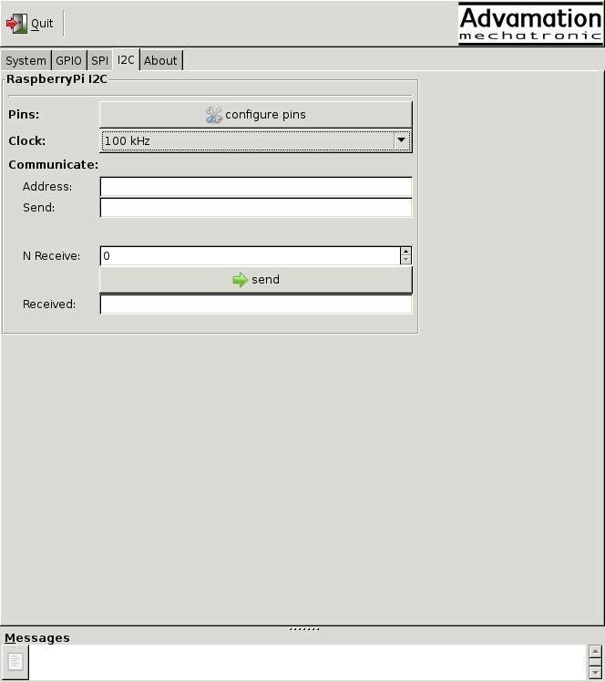
- graphical interface for many library functions
- JSON-RPC-interface
- framebuffer-driver for the TFT-display, to use it as default Linux display
- touchscreen driver for the TFT-touchscreen
Most of this software is Open Source under a MIT/X11-like license, which means that the sourcecode is freely available and may also be integrated into proprietary software. So, the provided example programs can serve as base for your own applications.
As demonstration, you'll find some screenshots of an example program (written in Python + GTK) below, which runs on a PC, connects with JSON-RPC over Ethernet to the Raspberry Pi and controls its I/Os. Hence, this program is ideal for starting up and testing the Raspberry Pi, the AdvaBoard and external periphery.
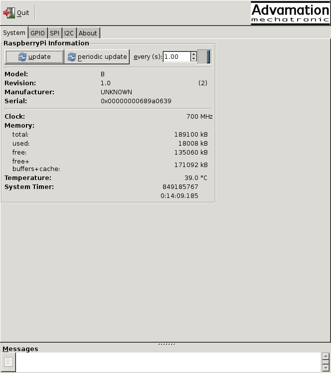
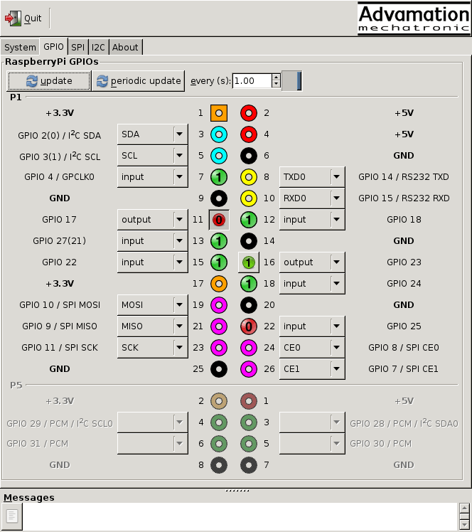
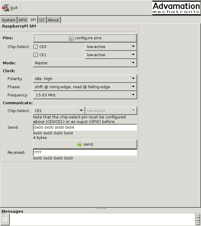
(click to enlarge)
technical information
(click to enlarge)
mechanics
- PCB-size: 96.5 * 64.8mm
- mounting holes:
- for a Raspberry Pi Rev. 2
- in all 4 corners (as generic mount, display-mount and/or fixation for a Raspberry Pis Rev. 1)
- weight: about 50g
- required power-supply: 5V, via 5V-power-supply-connector or via Raspberry Pi (switchable)
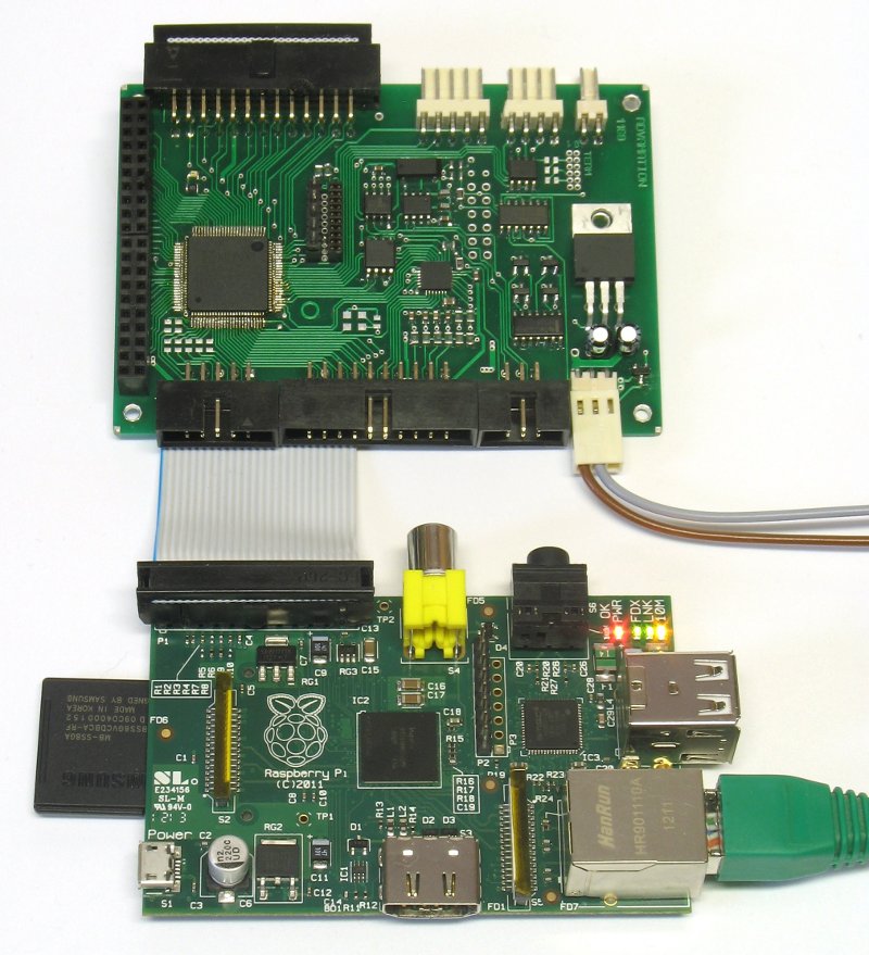
The AdvaBoard RPi1 an either be stacked directly above or below a Raspberry Pi, or mounted separately.
real-time clock / RTC
Unfortunately, the Raspberry Pi itself does not contain a real-time clock, so you usually have to either manually enter the current time and date or obtain them from the network (NTP) every time you boot your Raspberry Pi.
The AdvaBoard RPi1 solves this problem, by providing the Raspberry Pi with a (battery-backed) real-time clock. In addition, the real-time clock can be used to power-up the Raspberry Pi and the AdvaBoard on a certain time or in certain intervals (see power-supply / power-management), or to trigger some actions.
power-supply / power-management
The AdvaBoard RPi1 can
- either be powered from the Raspberry Pi and its Micro-USB-power-supply,
- or be powered from the 5V-power-supply-connector on the AdvaBoard, and then also power the Raspberry Pi
But there may always be only one of the two power supplies (5V-power-supply-connector on the AdvaBoard or power-supply on the Raspberry Pi), never both!
The 5V-power-supply-connector on the AdvaBoard should be preferred, since only then the AdvaBoard can turn the Raspberry Pi on and off. The power-management provides the following functions:
- switch the 5V-power-supply on and off (if an appropriate 5V supply is used)
- power-on of the 5V-power-supply at a certain time/on certain time intervals or when an I2C-interrupt occurs
- separately power-on/off the Raspberry Pi, E-SPI/RS-232/RS-485, CPLD and TFT-display by the integrated microcontroller at certain times or certain events
- battery-power for the real-time clock and selected I2C-sensors when the power-supply is switched off
Thereby, the AdvaBoard is perfectly suited for running from a larger battery or for self-contained operation with a solar panel, since the complete system (except the battery-powered real-time clock and maybe some I2C-sensors) can turn itself off, and wake up again depending on time or events. Directly after wakeup, the integrated microcontroller works and can e.g. poll some sensors and turn on additional components or the Raspberry Pi when needed.
To wake the AdvaBoard up, you can use a simple button, I2C-sensors with interrupt-output or an I2C-board including a microcontroller, which e.g. monitors some sensors.
5V-power-supply
Connector: PCB connector, 3 pins, pitch 2.54mm

|
| 5V-power-supply jack (male) |
| (mating view) |
| pin | signal | description |
|---|---|---|
| 1 | +5V | power-supply-input, 5V |
| 2 | GND | ground |
| 3 | PWR_ON | power-on/off control-line (low=on, high=off) |
battery
Connector: PCB connector, 2 pins, pitch 2.54mm

|
| battery jack (male) |
| (mating view) |
| pin | signal | description |
|---|---|---|
| 1 | +VBATT | battery-input, about +3V |
| 2 | GND | ground |
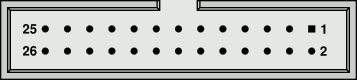
Raspberry Pi-connector
A 26-way ribbon cable is used to connect the AdvaBoard RPi1 with the Raspberry Pi.
Connector: IDC header, 26 pins, pitch 2.54mm
|
| Raspberry Pi jack (male) |
| (mating view) |
| pin | signal | description |
|---|---|---|
| 1 | 3.3V / NC | not connected |
| 2 | 5V | power-supply, 5V |
| 3 | SDA | I2C data |
| 4 | 5V | power-supply, 5V |
| 5 | SCL | I2C clock |
| 6 | GND | ground |
| 7 | I2CINT | I²C interrupt |
| 8 | TX | transmit data |
| 9 | GND | ground |
| 10 | RX | receive data |
| 11 | CPLD_P11 | CPLD-I/O |
| 12 | CPLD_P12 | CPLD-I/O |
| 13 | CPLD_P13 | CPLD-I/O |
| 14 | GND | ground |
| 15 | CPLD_P15 | CPLD-I/O |
| 16 | CPLD_P16 | CPLD-I/O |
| 17 | 3.3V / NC | not connected |
| 18 | CPLD_P18 | CPLD-I/O |
| 19 | MOSI | SPI master out/slave in |
| 20 | GND | ground |
| 21 | MISO | SPI master in/slave out |
| 22 | CPLD_P22 | CPLD-I/O |
| 23 | SCK | SPI clock |
| 24 | CE0 | SPI chip-select 0 |
| 25 | GND | ground |
| 26 | CE1 | SPI chip-select 1 |
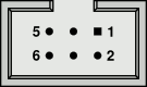
I²C / SMBus
The I2C-bus is by now the interface for digital sensors, e.g. for temperature-sensors, temperature-/humidity-sensors, acceleration-sensors, motion detectors etc.
The AdvaBoard here uses:
- 3.3V supply voltage
- 3.3V levels (not 5V-tolerant!)
- a separate wire for battery-power
- an interrupt-wire for fast response times and for waking up the AdvaBoard/Raspberry Pi on certain events
The pinout was thereby chosen in a way to minimize the crosstalk between SDA, SCL and the interrupt wire.
Connector: IDC header, 6 pins, pitch 2.54mm
|
| I2C jack (male) |
| (mating view) |
| pin | signal | description |
|---|---|---|
| 1 | GND | ground |
| 2 | SDA | serial data |
| 3 | +3.3V | power for external sensors |
| 4 | SCL | serial clock |
| 5 | +VBATT | battery power for external sensors |
| 6 | INT/ALERT | interrupt-input, low-active |
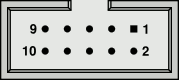
E-SPI
The SPI-interface offers a simple and very fast serial bus. It's especially suited for periphery which needs a high data rate or low latency, e.g. external CPLDs/FPGAs, displays etc.
The AdvaBoard here uses:
- 5V supply voltage
- 3.3V level, 5V-tolerant
- 4 additional address-wires
- an optional interrupt
The additional address-wires can either be used as normal chip-selects to altogether select 5 SPI-devices, or to select up to 16 devices with additional address-decoders. So, the "E-SPI" is perfectly suited to easily connect up to 16 external boards with ribbon cables to the AdvaBoard.
The address decoders can also include an interrupt logic, enabling the SPI-slaves to trigger interrupts (without any additional wires).
Connector: IDC header, 10 pins, pitch 2.54mm
|
| E-SPI jack (male) |
| (mating view) |
| pin | signal | description |
|---|---|---|
| 1 | +5V | power-supply for external periphery, switchable |
| 2 | SCK | SPI serial clock |
| 3 | MOSI | SPI master out/slave in |
| 4 | MISO | SPI master in/slave out / Interrupt |
| 5 | CS | SPI chip select |
| 6 | SEL0 | address-line 0 |
| 7 | SEL1 | address-line 1 |
| 8 | SEL2 | address-line 2 |
| 9 | SEL3 | address-line 3 |
| 10 | GND | ground |
digital-I/O / analog-I/O
The AdvaBoard includes several analog- and digital-I/Os:
- 8 digital-I/Os via CPLD with optional hardware-supported processing (e.g. for 2-phase-counters)
- 2 digital-I/Os via microcontroller incl. PWM, counter/timer, ...
- 4 analog-inputs (16 bit, 1 ksps) incl. voltage divider and filter
- 2 analog-outputs (8 bit, 0..0.25/0.5/1/2mA, max. 2.0V),
alternatively usable as digital-I/Os
Connector: IDC header, 20 pins, pitch 2.54mm
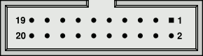
|
| I/O jack (male) |
| (mating view) |
| pin | signal | description |
|---|---|---|
| 1 | +3,3V | power for external electronics |
| 2 | GND | ground |
| 3 | AIN0 | analog-input 0, incl. voltage divider and filter-capacitor |
| 4 | AIN1 | analog-input 1, incl. voltage divider and filter-capacitor |
| 5 | AIN2 | analog-input 2, incl. voltage divider and filter-capacitor |
| 6 | AIN3 | analog-input 3, incl. voltage divider and filter-capacitor |
| 7 | AOUT0 | analog-output 0 / digital-I/O |
| 8 | AOUT1 | analog-output 1 / digital-I/O |
| 9 | IO0 | digital-I/O 0, e.g. PWM/frequency output, counter, comparator, ... |
| 10 | IO1 | digital-I/O 1, e.g. PWM/frequency output, counter, comparator, ... |
| 11 | CPLDIO0 | CPLD-I/O 0 |
| 12 | CPLDIO1 | CPLD-I/O 1 |
| 13 | CPLDIO2 | CPLD-I/O 2 |
| 14 | CPLDIO3 | CPLD-I/O 3 |
| 15 | CPLDIO4 | CPLD-I/O 4 |
| 16 | CPLDIO5 | CPLD-I/O 5 |
| 17 | CPLDIO6 | CPLD-I/O 6 |
| 18 | CPLDIO7 | CPLD-I/O 7 |
| 19 | +3,3V | power for external electronics |
| 20 | GND | ground |
RS-485 / EIA-485
The RS-485-interface is a robust and interference-proof industrial interface, which can be used to connect several devices (partly with hubs), and which is also suited for longer distances.
In addition to the RS-485-interface, the AdvaBoard also contains a RS-485-terminator, which can be activated/deactivated by a jumper. Furthermore, it's possible to use an automatic bit-modification to address the devices, which is e.g. necessary for the Advamation-RS-485-protocol.
Connector: PCB-connector, 4 pins, pitch 2.54mm

|
| RS-485 jack (male) |
| (mating view) |
| pin | signal | description |
|---|---|---|
| 1 | +12V / NC | not connected |
| 2 | RS-N | RS-485 more negative line when idle (about 2V to GND) |
| 3 | RS-P | RS-485 more positive line when idle (about 3V to GND) |
| 4 | GND | ground |
RS-232 TTL
The integrated RS-232-interface with TTL-levels can be used to connect various periphery, like e.g. a GPS or a radio module.
There's also a level-shifter available, which converts this interface to a normal RS-232-interface (with DB-9 female jack), and a USB-RS-232-adaptercable to connect this interface to USB.
Connector: PCB-connector, 5 pins, pitch 2.54mm
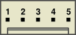
|
| RS-232 jack (male) |
| (mating view) |
| pin | signal | description |
|---|---|---|
| 1 | +5V | power for external periphery, switchable |
| 2 | +3.3V | power for external periphery |
| 3 | GND | ground |
| 4 | RX | receive data, 0..3.3V, 5V-tolerant |
| 5 | TX | transmit data, 0..3.3V, 5V-tolerant |
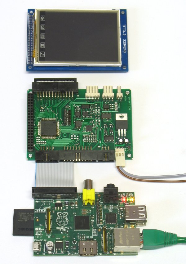
TFT-display-interface
The AdvaBoard contains an interface incl. controlling logic for digital TFT-displays. These displays can either be directly plugged/stacked on the AdvaBoard (and mounted to it), or connected to it with a ribbon cable and mounted separately.
There are currently TFT-displays available in the sizes 3.2" (320× 240), 4.3" (480×272), 5" (800×480) and 7" (800×480) -- all including a resistive touchscreen. The displays are fixed to a PCB which contains mounting holes, so the displays can be mounted to a front panel. Additionally, all displays contain a SD-card-slot.
Since the displays are controlled without using the Raspberry-Pi graphics chip, they are not intended for playing video or similar, but rather for graphical user interfaces (GUI) or as interactive data-display. However, framerates up to 50 fps (nearly 4 MPixel/s) can be achieved with the 3.2" display.
The display can be controlled both by the Raspberry Pi and the microcontroller of the AdvaBoard (e.g. to display a startup-screen). A framebuffer-driver, to use the display as default Linux-display (incl. X11), is also available.
In the future, it will be possible to connect additional TFT-displays to the AdvaBoard RPi1 via E-SPI.
For special applications, and when using an adapted version of the AdvaBoard and a special CPLD-firmware, it would even be possible to use the display-interface-pins as generic CPLD-I/Os (incl. hardware-supported processing by the CPLD).
Connector: IDC header, 40 pins, pitch 2.54mm
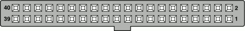
|
| TFT-display jack (female) |
| (mating view) |
| pin | signal | description |
|---|---|---|
| 1 | TFT_DB0 | display data line |
| 2 | GND | ground |
| 3 | TFT_DB1 | display data line |
| 4 | +3.3V | display power (3.3V) |
| 5 | TFT_DB2 | display data line |
| 6 | – | – |
| 7 | TFT_DB3 | display data line |
| 8 | TFT_RS | display control line |
| 9 | TFT_DB4 | display data line |
| 10 | TFT_WR | display control line |
| 11 | TFT_DB5 | display data line |
| 12 | TFT_RD | display control line |
| 13 | TFT_DB6 | display data line |
| 14 | TFT_DB8 | display data line |
| 15 | TFT_DB7 | display data line |
| 16 | TFT_DB9 | display data line |
| 17 | TP_SCK | touchscreen clock |
| 18 | TFT_DB10 | display data line |
| 19 | TP_CS | touchscreen chip-select |
| 20 | TFT_DB11 | display data line |
| 21 | TP_MOSI | touchscreen MOSI |
| 22 | TFT_DB12 | display data line |
| 23 | – | – |
| 24 | TFT_DB13 | display data line |
| 25 | TP_MISO | touchscreen MISO |
| 26 | TFT_DB14 | display data line |
| 27 | TP_IRQ | touchscreen interrupt |
| 28 | TFT_DB15 | display data line |
| 29 | SD_MISO | SD-card MISO |
| 30 | TFT_CS | display control line |
| 31 | SD_SCK | SD-card clock |
| 32 | – | – |
| 33 | SD_MOSI | SD-card MOSI |
| 34 | TFT_RESET | display control line |
| 35 | SD_CS | SD-card chip-select |
| 36 | LED_5V | Hintergrundbeleuchtung (5V) |
| 37 | – | – |
| 38 | LED_R | Hintergrundbeleuchtung (5V + Vorwiderstand) |
| 39 | – | – |
| 40 | – | – |
JTAG/C2-output
The AdvaBoard includes a JTAG- and a C2-output, which can be used to program Xilinx CPLDs/FPGAs and SiLabs C8051-microcontrollers. So, you don't need a separate programmer for external Xilinx-CPLD- or SiLabs-microcontroller-boards.
It's also possible to use these interfaces to update the AdvaBoard-firmware, e.g. to add further functionality later or to adapt the AdvaBoard to special applications.
